INSILCOTE ![]()
INTRODUCTION
The exceptional hydrophobicity of Insilcote inhibits the formation of continuous moist conductive layers on insulator surfaces. This, in turn, limits the flow of leakage currents thus preventing the creation of dry bands and partial discharges – critical steps in the flashover process.
The superior performance of silicone rubber over other insulating materials in polluted environments is well proven. What makes silicone unique is the fact that, owing to the migration of low molecular weight silanes that exist within the elastomer, the water repellent properties are imparted to contaminants which accumulate on the surface.


Uncoated porcelain – pollution wets and On a silicone surface, the pollution
forms a conductive layer becomes hydrophobic
Figure 1: Hydrophobicity Transfer
The constant water-repellency exhibited by Insilcote coated insulators, even in the most severe environments, coupled with silicone’s inherent resistance to degradation by ultra-violet radiation, ozone and most chemicals, combined with the use of specialised fillers to combat power arc damage, enables the material to provide enhanced system reliability over a period of many years.
Since its release to the market in 1991, Insilcote HV2000 has been in service in the most polluted areas of Southern Africa, and has also found application in Europe, North America, Australasia and the Middle East. No flashovers have been experienced at any of the treated sites.
The material's usage has ranged from small 11kV Substations to complete 400kV Transmission Stations and 533kVDC Converter Stations. The operating environments include marine salt fogs, coastal desert conditions, heavily industrialised sites with, for example, acidic emissions, power station fall-out and heavy cement dust contamination, and agricultural areas characterised by sugar cane burning and the use of highly conductive fertilisers and weedkillers.
Insilcote HV2000 also forms part of Mace Technologies' Insilcure insulator upgrading system. Because of the vast variety of insulator designs in substation yards, Insilcure was developed to evaluate and treat each insulator individually and provide a comprehensive engineering approach to pollution problems. A description of the Insilcure process is available on request.
DEVELOPMENT BACKGROUND
By the early 1990's the superior performance of silicone rubber in polluted areas had been well demonstrated and most of the country's major overhead lines were being re-insulated with composite long rods. Substations, however, remained a problem. This prompted the formulation of Insilcote in 1991 as a joint development project between Mace Electrical Technologies and the Electric Power Research Group of the University of the Witwatersrand with a view to significantly reducing maintenance costs and eliminating contamination flashover.
The project was led by Professor J P Reynders of the University. He is a recognised expert in the field of high voltage dielectric materials and phenomena and has served terms as the South African member of Cigre Study Committee 33 (Power System Insulation Co-ordination) and as Chairman of the South African National Committee of Cigre.
Mace Technologies was represented by R Macey, who studied the behaviour of polluted insulators for his undergraduate BSc(Eng) thesis in 1971 and later obtained an MSc(Eng) degree on this subject in 1981. He worked for Eskom's Research Division for 6 years specialising in insulator contamination and mitigation measures and established the first local natural insulator testing sites in 1973. Before founding Mace Technologies in 1990, he worked for 12 years with the Cullinan Group where he promoted the use of silicone rubber insulators and designed all the porcelain insulators manufactured in the country during this period. He is a Distinguished Member of Cigre, is on the Executive Board of the Cigre National Committee and is active in Working Group B2-21 (Insulators). He has also served as South Africa's member of Cigre Study Committee B2 (Overhead Lines).
TECHNICAL DESCRIPTION
Insilcote is extremely hydrophobic displaying a water droplet contact angle of around 100 degrees. Moreover, the coating has a quick hydrophobicity recovery rate and, by the migration of low molecular weight silanes present in the material, readily transfers its hydrophobic characteristics to any covering contaminating layer. Curves indicating these effects are provided below.


For improved performance, and a controlled cure at room temperature, Insilcote is a two-part material, i.e. a small volume of catalyst is poured into the coating before application. Unlike those materials utilising an oxime cross-linking agent, Insilcote's curing system has the benefits of not requiring any atmospheric moisture for vulcanisation to take place, the cure rate is independent of humidity, no by-products are released on curing and there is practically no shrinkage (<0,1% versus 0,5% to 1% for oxime systems). The shelf life is also much longer than single-part rubbers.
The coating is designed for spray application to give an optimum layer thickness of 0,3 to 0,5mm and is formulated with various solvents for ease of application and to yield a smooth, uniform, high quality finish.
The coating has a typical skin-over time of 15 minutes. Unlike the one-part rubbers, its curing time is consistent as it is independent of the ambient humidity. In order to minimise waste and for ease of handling, after addition of the catalyst the coating has a pot life of one hour at 23°C. The equipment can be energised immediately after coating.

Although the coating does have some adhesion to porcelain and glass, the application of Insilcote Primer, which is supplied with all coating purchased, is recommended to provide a strong permanent bond to all ceramic, glass and resin materials. If a separate primer is not used, the bonding agent must be included in the coating. This, of course, replaces some of the silicone and thus adversely affects the material performance and longevity. It is our philisophy that primer be applied only at the interface between the insulator and the coating where it is needed, and leave the rubber layer itself free of unnecessary materials.
The national utility, Eskom, has undertaken comprehensive evaluation of coating materials over a number of years at their Koeberg Insulator Pollution Testing Station. Situated on the west coast of the country, the various energised samples are exposed to the extreme marine conditions characteristic of the site. Physical degradation, leakage current amplitudes and flashover occurrence are closely monitored. As an example of the results achieved at this facility, Figure 2 shows the relative cumulative leakage current flow on three identical insulators – two of which are coated with different brands of silicone rubber and the third left uncoated. It is evident that the silicone rubber significantly improves the insulator performance and, further, that the extent of the improvement is dependent on the type of rubber used.
Figure 2: Accumulated coulomb ampere leakage currents measured on coated and
uncoated porcelain insulators over a period of one year.
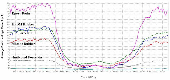
The performance of a porcelain insulator coated with Insilcote HV2000 compared to units geometrically identical but of different materials, is illustrated in Figure 3. It is interesting to note that the leakage currents on the coated porcelain are significantly less than even the silicone rubber composite unit. This is due to the more efficient thermal transfer possible through the Insilcote layer to the ceramic substrate.

Figure 3: Average leakage current amplitudes in relation to time-of-day, measured on
identical insulators of various material over a one year period.
Since its introduction in 1991, Insilcote HV2000 has exhibited exceptional performance with no pollution flashovers being experienced even in the most severe of environments and in cases where the insulators to which it was applied are considerably under-dimensioned for the environment in which they are expected to operate.
To date, over 200 substations, ranging in voltage from 66kVAC to 400kVAC and up to 533kVDC have been coated. The first applications undertaken on the northern coast of Kwa-Zulu Natal still maintain their hydrophobicity after 15 years service. This, in spite of the high pollution severity of the area, comprising marine fogs, agricultural pollution from sugar cane burning and crop spraying, and industrial fall-out from the nearby fertiliser plants, coal terminal and aluminium smelter.
Brief descriptions of the experience at a few specific sites, which illustrate how Insilcote HV2000 really does serve to prevent insulator flashover under adverse conditions, are provided below.
In 1997, the main apparatus bushings of the 533kVDC Apollo Converter Station were Insilcoted. The client's order excluded the treatment of the bridge and capacitor bank support insulators as they considered these to be of adequate creepage distance.
In July 2001, during the occurrence of some unseasonal mists, both the bridge and capacitor supports flashed over – even though they possessed considerably greater creepages than the Insilcoted bushings which did not flash or, in fact, show any signs of leakage current activity.


In 1998, following several flashovers, the 132kV and 400kV yards of Hendrina Power Station were Insilcoted. At the time, Mace Technologies recommended the replacement of the glass disc strung busbar strings with silicone rubber composite long rods. The utility, however, stated that no problem with these insulators had been experienced in the 21 years that the power station had been in operation. In view of the dirty appearance of the discs, they did, though, install new glass strings. In the spring of 1999, these flashed over, resulting in the total shutdown of this 2000MW generation facility.
This indicates that the Insilcote solved the problem of the flashover of the post and apparatus porcelains. However, the problem then manifested itself on the next weakest link - the busbar strings. (Needless to say, these were urgently replaced with appropriately dimensioned silicone rubber units).
A flashover at this substation was again experienced in 2000. On investigation, it was found that a 132kV isolator (disconnector) installed 10 months previously but left un-coated, was the cause of the fault. This again demonstrates that new insulators can fail in under a year at this site. The Insilcoted porcelains have now displayed over nine years of trouble-free service and show no signs of deterioration.


Whites North 88kV Substation in the town of Lichtenburg is located within the premises of an active cement works. As such, it is subjected to continual cement dust contamination which builds up and hardens on the surfaces of all apparatus, forming layers up to 4mm thick. Of course, flashover of the insulation was common.


Typical cement dust pollution at the Whites North Substation
Although concerned that the large amount of contamination present may overwhelm the beneficial properties of a silicone rubber coating in a fairly short period, it was decided to increase the specific creepage distance of the insulators to 31mm/kV by means of Insilshed shed extenders followed by the application of Insilcote. This was completed during the first quarter of the year 2000.

EPDM composite insulators used on the strung busbars of
Whites North Substation were eroded to the core in under two years.
During October 2003, a transformer was replaced but the new unit and its associated surge arresters were left uncoated. In February 2004, two of the HV bushings and one of the arresters flashed over. The rest of the yard remained unaffected. The upgraded insulation had thus served for four years without problem whereas new untreated porcelains failed within four months of exposure at this site.
TECHNICAL CHARACTERISTICS
| As Supplied - |
|
| Appearance after mixing............................................... | Light blue liquid |
| Specific Gravity at 25degC........................................... | 1,01 |
| Viscosity..................................................................... | 33,5cSt |
| As Cured - | |
| Specific Gravity at 25 degC.......................................... | 1,18 |
| Dielectric Strength....................................................... | 64kV/mm |
| Permittivity.................................................................. | 2,4 |
| Surface Resistivity....................................................... | 1,5 x 10¹³ ohms |
| Volume Resistivity........................................................ | 2,29 x 10¹³ ohm-metres |
| Loss Tangent at 50Hz................................................... | 0,0096 |
| Flammability under dry arcing....................................... | No visible flame No smouldering |
CIGRE PAPER ON ELIMINATION OF POLLUTION FLASHOVER IN SUBSTATIONS
DOWNLOADABLE BROCHURES/PAMPHLETS

INSILCURE
HAWKEYE
REDEYE
COND JOINTS